Article 2: What is a fiber optic spectrometer, and how do you choose the appropriate slit and fiber?
Fiber optic spectrometers currently represent the predominant class of spectrometers. This category of spectrometer enables the transmission of optical signals through a fiber optic cable, often called a fiber optic jumper, which facilitates enhanced flexibility and convenience in spectral analysis and system configuration. In contrast to conventional large laboratory spectrometers equipped with focal lengths typically ranging from 300mm to 600mm and employing scanning gratings, fiber optic spectrometers employ fixed gratings, eliminating the need for rotating motors. The focal lengths of these spectrometers are typically in the range of 200mm, or they can be even shorter, to 30mm or 50mm. These instruments are highly compact in size and are commonly referred as miniature fiber optic spectrometers.
Miniature Fiber Spectrometer
A miniature fiber optic spectrometer is more popular in industries due to its compactness, cost-effectiveness, fast detection capabilities, and remarkable flexibility. The miniature fiber optic spectrometer typically comprises a slit, concave mirror, grating, CCD/CMOS detector, and associated drive circuitry. It is connected to the host computer (PC) software via either a USB cable or serial cable to complete the spectral data collection.
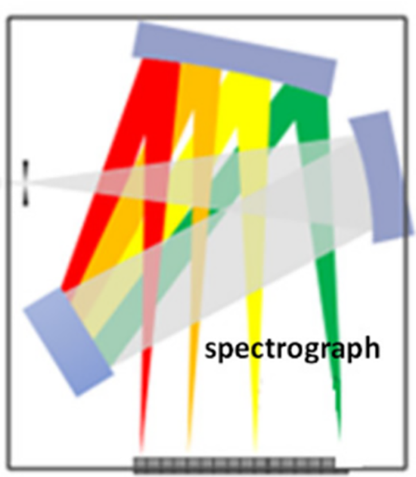
Fiber optic spectrometer structure
The fiber optic spectrometer is equipped with a fiber interface adaptor, provides a secure connection for optical fiber. SMA-905 fiber interfaces are used in most fiber optic spectrometers yet some applications require FC/PC or non-standard fiber interfaces, such as the 10mm diameter cylindrical multi-core fiber interface.
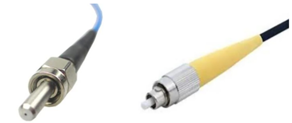
SMA905 fiber interface (black), FC/PC fiber interface (yellow). There is a slot on the FC/PC interface for positioning.
The optical signal, after passing through the optical fiber, will first go through an optical slit. The miniature spectrometers typically use non-adjustable slits, where the slit width is fixed. Whereas, JINSP fiber optic spectrometer offers standard slit widths of 10μm, 25μm, 50μm, 100μm, and 200μm in various specifications, and customizations are also available according to user requirements.
The change in slit widths can impact light flux and optical resolution commonly, these two parameters exhibit a trade-off relationship. Narrower the slit width, higher the optical resolution, albeit at the expense of reduced light flux. It's essential to note that expanding the slit to increase light flux has limitations or is nonlinear. Similarly, reducing the slit has limitations on the achievable resolution. Users must assess and select the suitable slit in accordance with their actual requirements, such as giving priority to light flux or optical resolution. In this regard, the technical documentation provided for JINSP fiber optic spectrometers includes a comprehensive table correlating slit widths with their corresponding resolution levels, serving as a valuable reference for users.
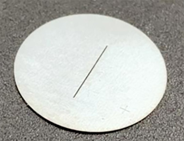
A narrow gap
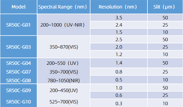
Slit-Resolution Comparison Table
The users, while setting up a spectrometer system, need to choose appropriate optical fibers for receiving and transmitting signals to the spectrometer's slit position. Three important parameters are required to be considered when selecting optical fibers. The first parameter is the core diameter, which is available in a range of possibilities including 5μm, 50μm, 105μm, 200μm, 400μm, 600μm, and even larger diameters beyond 1mm. It is important to note that increasing the core diameter can enhance the energy received at the front end of the optical fiber. However, the width of the slit and the height of the CCD/CMOS detector limit the optical signals that the spectrometer can receive. So, increasing core diameter doesn't necessarily improve sensitivity. Users should choose the appropriate core diameter based on the actual system configuration. For B&W Tek's spectrometers using linear CMOS detectors in models like SR50C and SR75C, with a 50μm slit configuration, it is recommended to use a 200μm core diameter optical fiber for signal reception. For spectrometers with internal area CCD detectors in models like SR100B and SR100Z, it may be suitable to consider thicker optical fibers, such as 400μm or 600μm, for signal reception.
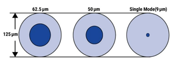
Different optical fiber diameters
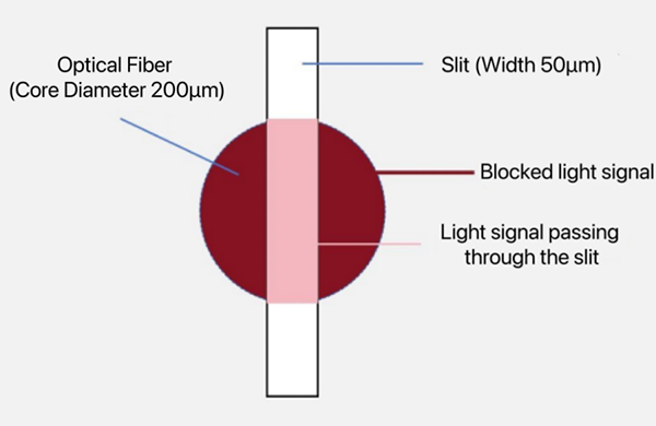
Fiber optic signal coupled to the slit
The second aspect is the operating wavelength range and materials of optical fibers. Optical fiber materials typically include High-OH (high hydroxyl), Low-OH (low hydroxyl), and UV-resistant fibers. Different materials have different wavelength transmission characteristics. High-OH optical fibers are typically used in the ultraviolet/visible light range (UV/VIS), while Low-OH fibers are used in the near-infrared (NIR) range. For the ultraviolet range, special UV-resistant fibers should be considered. Users should choose the appropriate optical fiber based on their operating wavelength.
The third aspect is the numerical aperture (NA) value of optical fibers. Due to the emission principles of optical fibers, the emitted light from the fiber end is confined within a certain divergence angle range, which is characterized by the NA value. Multi-mode optical fibers generally have NA values of 0.1, 0.22, 0.39, and 0.5 as common options. Taking the most common 0.22 NA as an example, it means that the spot diameter of the fiber after 50 mm is approximately 22 mm, and after 100 mm, the diameter is 44 mm. When designing a spectrometer, manufacturers typically consider matching the optical fiber's NA value as closely as possible to ensure maximum energy reception. Additionally, the NA value of the optical fiber is related to the coupling of lenses at the front end of the fiber. The NA value of the lens should also be matched as closely as possible to the NA value of the fiber to avoid signal loss.
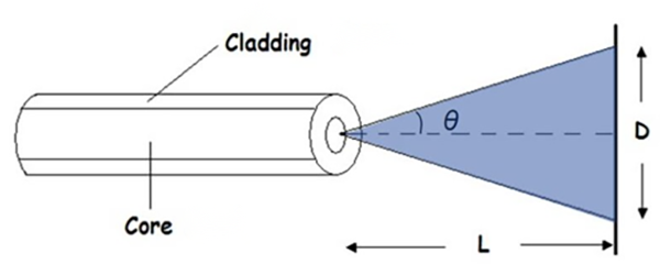
The NA value of the optical fiber determines the divergence angle of the optical beam
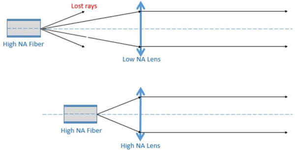
When optical fibers are used in conjunction with lenses or concave mirrors, the NA value should be matched as closely as possible to avoid energy loss
Fiber optic spectrometers receive the light at angles determined by their NA (Numerical Aperture) value. The incident signal will be fully utilized if the NA of the incident light is less than or equal to that spectrometer’s NA. Energy loss occurs when the NA of incident light is greater than NA of spectrometer. In addition to fiber optic transmission, free-space optical coupling can be used to collect light signals. This involves converging parallel light into a slit using lenses. When using free-space optical paths, it is important to choose appropriate lenses with an NA value matching that of the spectrometer, while also ensuring that the spectrometer's slit is positioned at the focus of the lens to achieve maximum light flux.
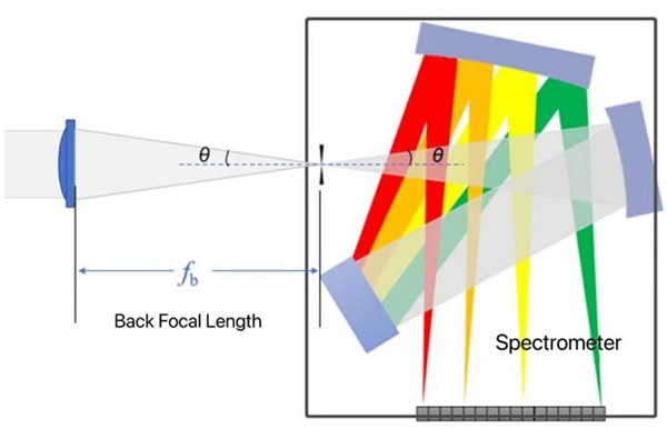
Free space optical coupling
Post time: Dec-13-2023